Mapping Nodes
The Node Mapping form is opened by pressing the “Map Nodes” button on the configuration form. This button is only activated if more than one FEM has been read and different models are chosen in the test and analysis pulldowns in the "Select Test / Analysis Geometry" Panel. Additionally, one of those FEMs has to be the analysis bulk data. The purpose of the Node Mapping form is to create a relation between test geometry and analysis geometry in the common case where the test nodes do not have corresponding, identically numbered nodes in the analysis model. It is critical to note that this is a mapping of nodes only. Degrees of freedom are not reordered, nor are coordinate transformations applied.
When the Node Mapping form is initially opened, the Test Model table and the Analysis Model table in the FEM data panel will be populated with nodes of the test model selected in the Display region, and the analysis model loaded as bulk data. The filename of the test and analysis models are displayed directly above the table. If different test geometry is desired for the mapping, a new file can be selected from the pulldown in the Test Geometry panel in the upper left-hand corner of the form. This pulldown will refresh the test model and in turn remove any matches that had been made with the previously selected model. This pulldown will contain all FEMs that were listed in the test display geometry pulldown on the Configuration Creation form.
The easiest way to create a node map is to press the “Auto Match” button. This button will generate matches based on the threshold and method that are selected at the top of the form. The “Threshold” controls the maximum distance between two nodes that will be considered for a match. The Method panel controls whether the “Best Unique” or “Best Overall” node match will be considered when automatically making matches. Matches can also be manually made by selecting a node from the Test Model table and a node from the Analysis Model table and pressing the “Assign” button. After the button is pressed, the match will be added to the Matches table. A previously defined match can be removed by selecting the desired match in the Matches table and pressing “Clear.” All matches can be removed by pressing the “Clear All” button. Nodes that have been matched will be grayed out in the Test Model and Analysis Model tables.
In the case that “Auto Match” cannot match all of the test nodes, the “Mark Problems” button will turn red all rows of the Matches table corresponding to unmatched nodes This list of problematic matches can be navigated by pressing the up or down arrows to the right of the “Mark Problems” button. This will automatically navigate the table to the next or previous problematic match. If no problematic matches exist and all test nodes are mapped, then a dialog box will appear confirming this.
To manually find the best match for a particular test node, select the desired test node and press “List Closest Nodes.” This form lists the ten closest nodes to the selected test node. Marking a checkbox on the table and pressing “Save” will assign that match and update the Matches table. Analysis nodes that already have a match will be grayed out. Selecting any of these nodes will update the current match and remove the previously defined match for that analysis node if the match method is currently “Best Unique.”
The matching process can be visualized by pressing the “Plot FEMs” button. This form will plot both the test and the analysis FEMs. If the “Overlay Test/Analysis FEM” checkbox is checked, both FEMs will be plotted in the same window. Otherwise, they will be plotted in separate windows. Selecting this checkbox with the FEM already plotted will switch the windows being shown. Checking the “Display Axes” checkbox will display the axes in the figures. Checking “Link Windows” will cause the test and analysis FEM windows to move together. This does not apply to the figure containing the overlaid FEM.
If the FEMs are not overlaid, selecting a node from the Test Model or Analysis Model tables will plot the node as a blue circle on the corresponding FEM. Selecting a match from the Matches table will plot the selected test/analysis node as a blue square on their corresponding FEMs. If the FEMs are overlaid, the selections will be treated identically but will be plotted on the same figure.
The node map can be saved by pressing the “Save” button. If all nodes are not matched, a dialog box will appear asking if the test shapes should be truncated. If they should be truncated, the DOF corresponding to the unmatched nodes will be removed from the shape.
After the node map has been saved, the form will close and the Active Transform panel will confirm that the nodes have been mapped. Upon reloading a configuration, the mapping will be automatically applied to the test shapes. If the map needs to be removed, reopen the Node Mapping form, select “Clear All,” and then save the map. The Active Transform panel will then indicate that the nodes are not longer mapped.
An alternative capability to the automatic node mapping is provided by the "Import" button. The user can specify the node mapping directly in a text file. This option could be especially important if the test nodes may map to coincident nodes in the analytical model. The file should contain two columns of numbers separated by commas. The first column contains the test node ID. The second column contains the corresponding analysis node ID. There must not be copies of any test node ID. If the map does not include all of the test nodes, the user will be prompted if they want to continue. If so, the test shapes will be truncated to the nodes listed in the file.
After the node mapping has been set, the user can save the mapping to a text file using the "Export" button. The mapping will be saved as a comma-delimited text file with two columns: test node IDs and analysis node IDs. The user will be provided with a file selection window to choose the name and location of the file.
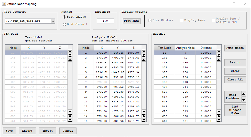
Node mapping interface.
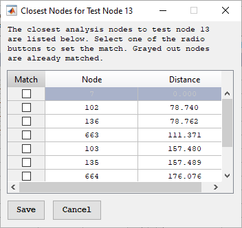
Closest node form for node mapping.